
Necessary cookies are absolutely essential for the website to function properly. FET Constant Current Sources in Circuits.Wide Bandwidth JFET Operational Amplifiers.For low level drain battery voltage, the source to drain current may flow in either direction since the source and drain are interchangeable. By narrowing the channel, the resistance of the source to drain channel is increased. Applying moderate reverse bias can increase the thickness of the depletion region. The degree of reverse bias controls the conduction. The N-type bar would conduct in either direction because of doping if a voltage was applied between the source and drain. The JFET cross-section image shown below is a properly biased JFET where the gate is reverse and constitutes a diode junction to the source to drain semiconductor slab. – The polarity of the biasing voltage needs to be reversed – Channel current is positive due to holes Schematic Symbols of JFET The P-channel JFET operates the same as the N-channel with the following exceptions: The schematic symbols of N-channel and P-channel JFETs are shown below.

The flow of electric charge through a JFET is controlled by constricting the current-carrying channel as compare to a garden hose where the flow of water is controlled by squeezing it reduce the cross section. For a P-N junction to occur at the interface, the gate terminal should have doping opposite to that of the channel which surrounds it.

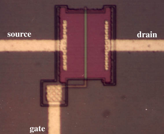
The JFET is doped to contain an abundance of positive or negative charge carriers since it is a long channel of semiconductor material. The distance between the drain and source is important and should be kept to a minimum whatever the material used for the FET. Using epitaxy or by diffusing the impurities into the substrate or by ion implantation, the active N-type region may be grown. A heavily doped substrate normally acts as a second gate for silicon devices. Gate voltage that controls drain currentįETs can be fabricated in a number of ways.For low frequency operation, source and drain can be interchanged.For a given value of source-to-drain voltage, this reduces the current flow. The majority carriers from a larger depletion zone around the gate are depleted when the gate is made more negative. The depletion of charge carriers from the N-channel serves as the control element for the JFET. The input impedance is extremely high since the gate junction is reverse biased and because there is no minority carrier contribution to the flow through the device. Since electrons have a higher mobility through a conductor compared to holes, N-channel JFETs have a greater channel conductivity compared to their equivalent P-channel type. The P-channel is doped with acceptor impurities on where the flow of current is positive in the form of holes. The N-channel is doped with donor impurities where the flow of current through the channel is negative in the form of electrons. The junction FET has a channel consisting of N-type semiconductor or P-type semiconductor material and the gate is made of the opposite semiconductor type. The Junction Field Effect Transistors (JFET) has a channel consisting of N-type semiconductor or P-type semiconductor material and the gate is made of the opposite semiconductor type.


 0 kommentar(er)
